Agenda
- Purchase required hardware
- Print with 3D printer needed cases
- Assemble coupler
- Assemble MOD-IO
- Connect the coupler and MOD-IO
- Power up devices and connect peripherals
Requirements
- A real physical Coupler device and one MOD-IO device
- a 3D printer
- USB keyboard and mouse
- basic assembly skills
Goal
This how to explains how to build yourself an OPC UA coupler from scratch. At end of this how to you will have a real physical Coupler device to use in automation projects as seen below.
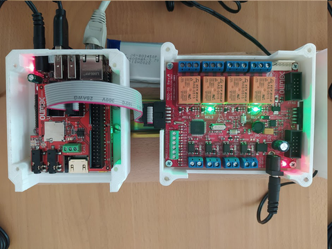
Figure 1: a rPLC Coupler (with attached MOD-IO to the right.) running the "Hello World!" PLC program here.
Above is the Coupler device which you will build (cover plates are removed for visibility).
Purchase required hardware
A coupler consists of at two cases:
- The Coupler itself (in left part in the image) which consists of a SOC board (STMP157-OlinuXinu-LIME2-EXT) and a shield on top (STMP15X-SHIELD) where the shield that provides UEXT connectivity to MOD-IO devices
- one of many (up to 127) MOD-IO boxes which are connected to coupler over UEXT cable (the right part in the image).
Assemble coupler
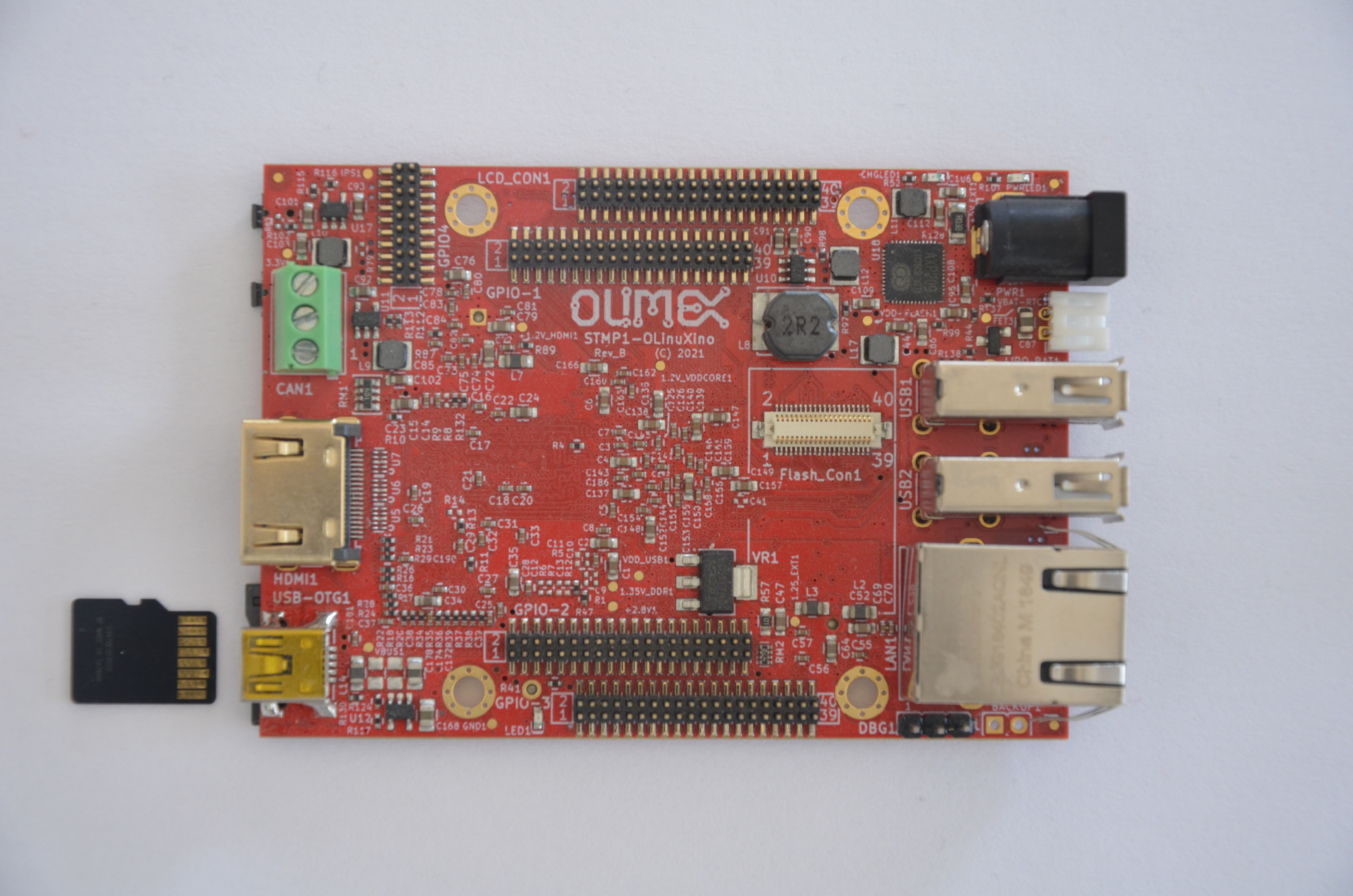
Step1: Install the micro SD card first into the coupler
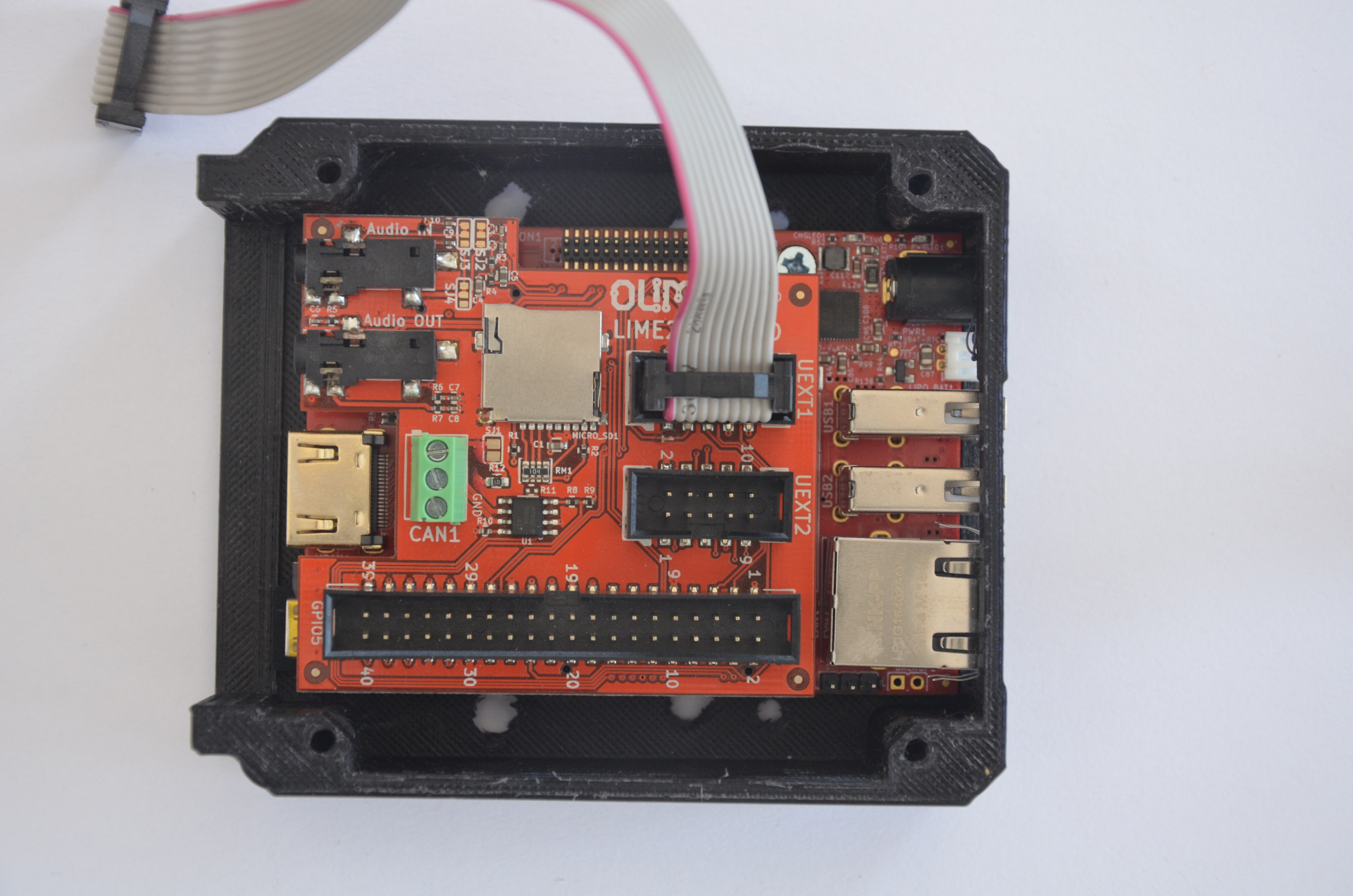
The first thing we need to do is to insert the micro SD card into the designated slot as show in the picture below.
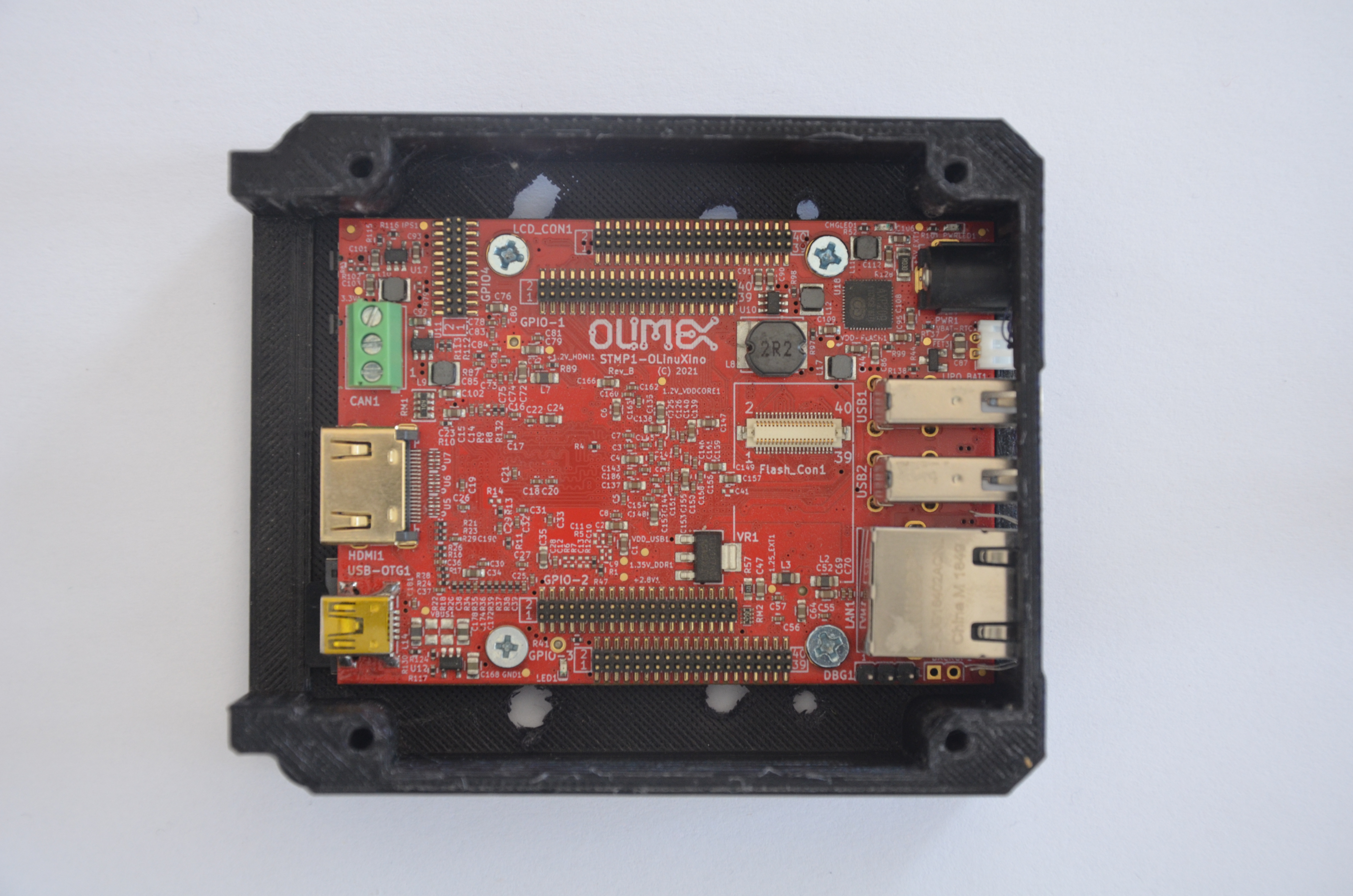
Step 2: Connect coupler to its bottom case
The second step is to connect the coupler bottom case with board from step 1. For this we use 4 screws (XXX: dimensions) as shown in picture below.
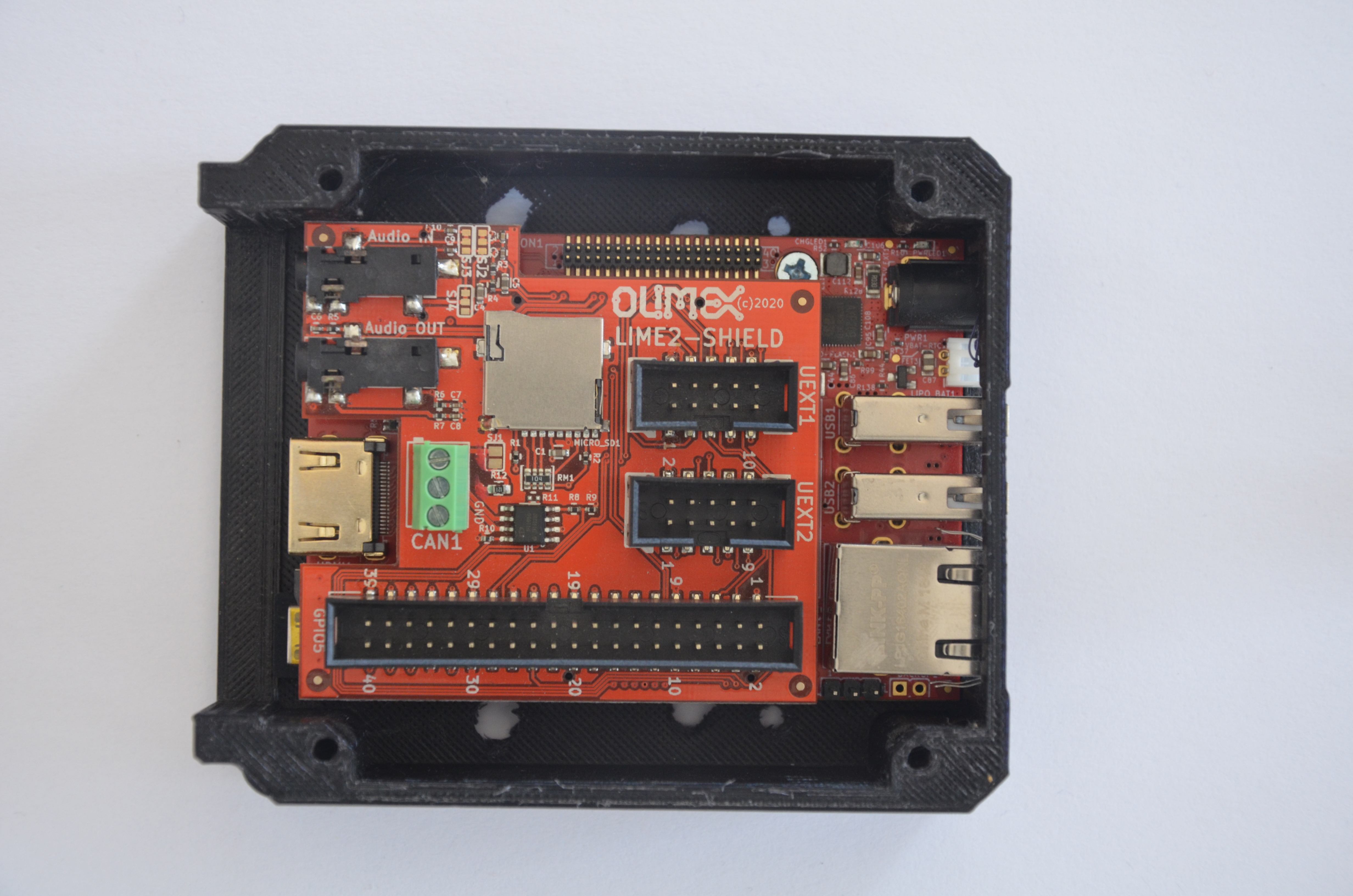
Step 3: Connect the shield
We need to connect the shield board by placing it on top of the case and board from step 2. Mind to properly match all the pins as this potentially can lead to an electrical damage.
Step 4: Connect the UEXT cable
As later one we will close the case we need to install the connecting cable (UEXT) to MOD-IO now. Please connect to UEXT1 slot.
Step 5: Put top cover plate
The last step is to close the case with its top cover plate by 4 screws.
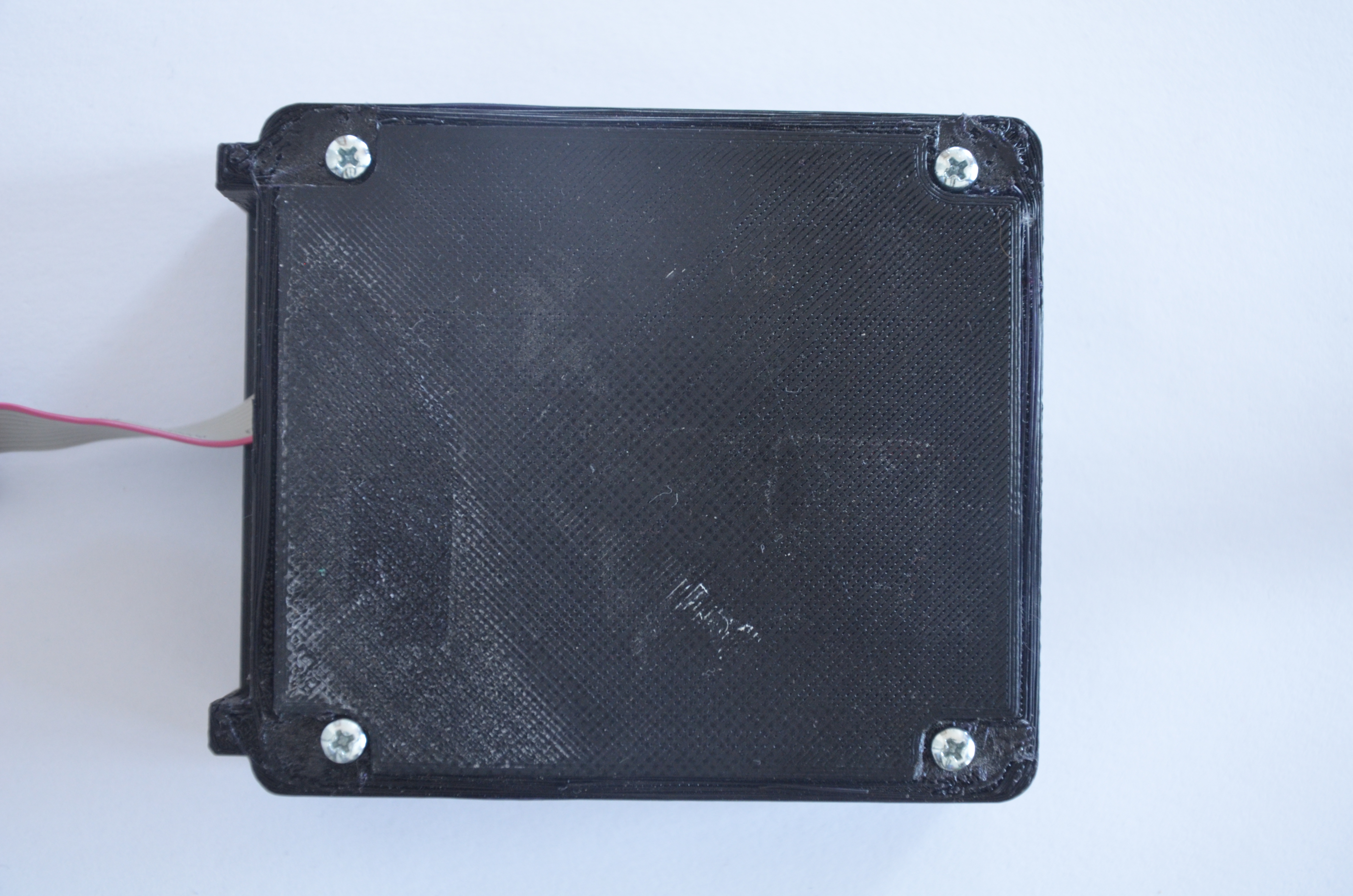
The coupler is ready.
Assemble MOD-IO
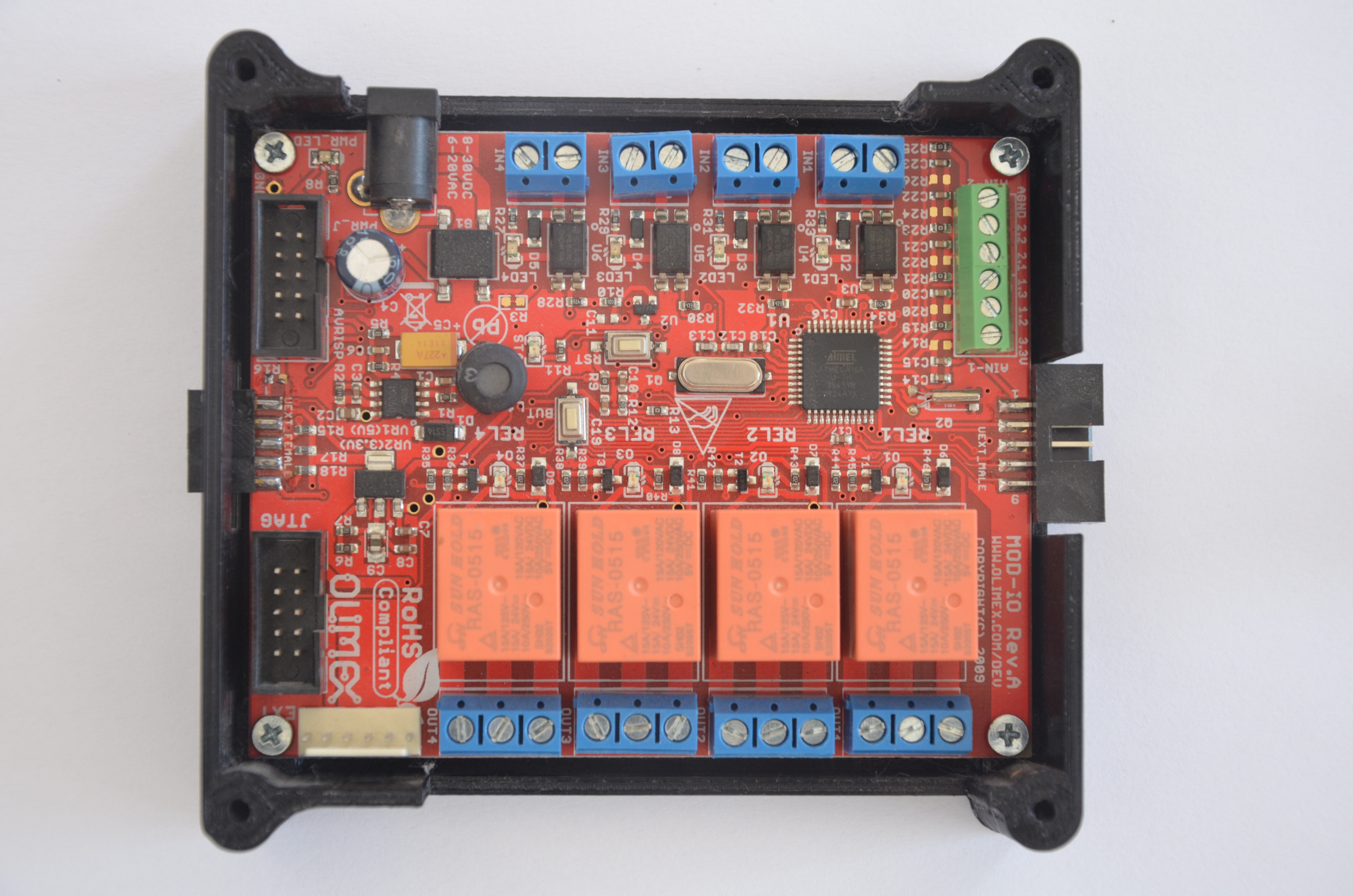
Step 1: Attach to MOD-IO's bottom case the MOD-IO board using 4 screws in the designated montage holes as shown below.
Step 2: Place top MOD-IO plate
The MOD-IO is ready.
Connect the coupler and MOD-IO
Step 1: Connect the boxes using the UEXT cable
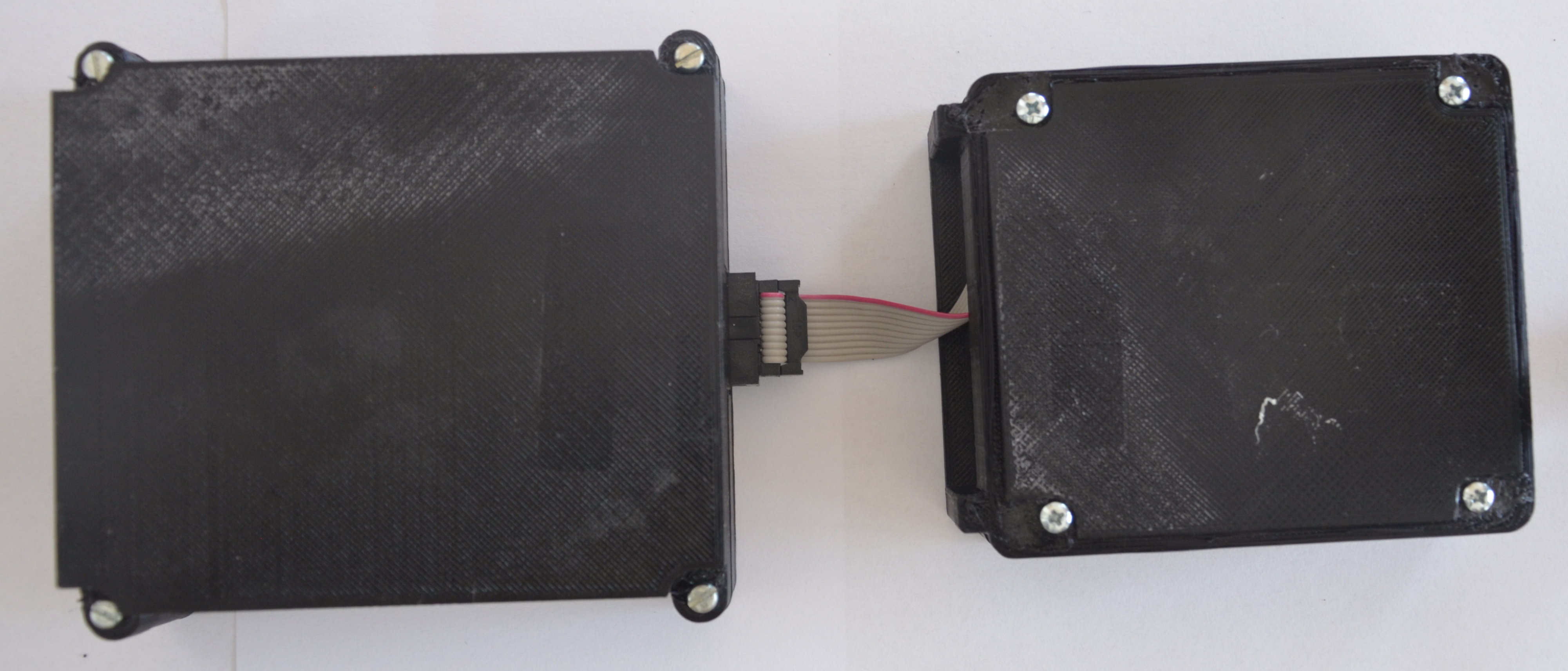
- Stick the two boxes next to each other (to the most left side the coupler and next to it MOD-IO)
- Connect using UEXT cable the boxes (XXX: define name opf the ports on the boards)
- Place the top cover of the coupler and screw the four connecting screws.
- Place the top cover of the MOD-IO and screw the four connecting screws.
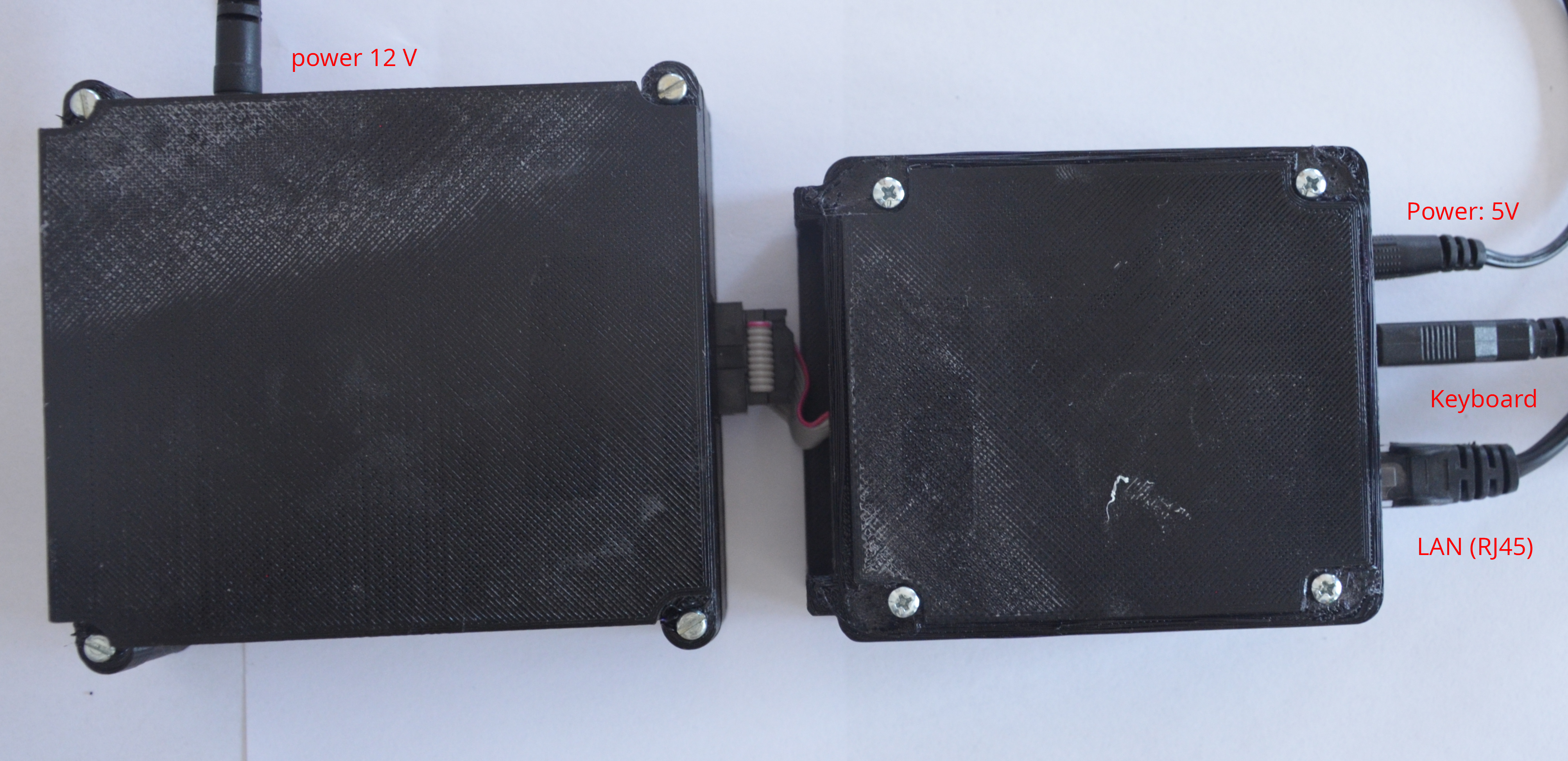
Power up devices and connect peripherals
Please follow the following procedure:
- Connect a 5V power supply to the coupler.
- (optionally) if you have a battery connect it as well to the designated port.
- Connect a 12V power supply to MOD-IO
- Connect an USB keyboard and a mouse
- Connect the coupler to the local LAN
At the end it should be same as picture below.
Success
Now you have all needed hardware up and ready. Next step is install OS on the coupler.